The field of percutaneous structural heart interventions has grown tremendously in recent years. This growth has fueled the development of new imaging protocols and technologies in parallel to help facilitate these minimally-invasive procedures. Fusion imaging is an exciting new technology that combines the strength of 2 imaging modalities and has the potential to improve procedural planning and the safety of many commonly performed transcatheter procedures. In this review we discuss the basic concepts of fusion imaging along with the relative strengths and weaknesses of static vs dynamic fusion imaging modalities. This review will focus primarily on echocardiographic-fluoroscopic fusion imaging and its application in commonly performed transcatheter structural heart procedures.
Keywords
In the last decade the field of percutaneous transcatheter structural heart interventions has grown exponentially. Due to advances in both technology and procedural techniques, multiple structural procedures, including transcatheter aortic valve replacement (TAVR), transcatheter mitral valve repair, paravalvular leak closure, left atrial appendage occlusion, and many other techniques are commonly being performed in the cardiac catheterization laboratory worldwide. Along with these minimally-invasive techniques has come a greater need for precise preprocedural and real-time intraprocedural imaging guidance to facilitate safe and successful repair procedures without the availability of direct visualization provided by open heart surgery. A central challenge of fluoroscopic imaging during intracardiac structural procedures is the challenge of correlating patient anatomy with 2-dimensional (2D) fluoroscopic views. Fusion imaging is a novel technological advance that allows for integration of highly detailed echocardiographic, computed tomographic, and magnetic resonance cardiac imaging with fluoroscopy. This review will cover the basic principles of fusion imaging and also detail specific clinical applications of echocardiographic-fluoroscopic fusion imaging for a variety of percutaneous transcatheter structural heart procedures.
FUSION IMAGING: BASIC CONCEPTSIn contrast to open heart surgery, percutaneous structural interventions do not permit direct visualization of the cardiac anatomy and pathology and, as a result procedural success, is dependent on imaging guidance. Optimal imaging in structural heart disease provides a 3-dimensional (3D) image that matches the underlying anatomic pathology, allowing procedural planning, intraprocedural guidance, and postprocedure assessment. Traditionally, fixed-projection 2D-fluoroscopy has been the primary imaging tool for interventional cardiologists. Fluoroscopy provides visualization of the position and course of interventional catheters and wires in a wide field of view. Biplane fluoroscopy helps by providing a second 2D projection usually in an orthogonal plane to the first projection to guide 3D navigation within the cardiovascular system. The addition of contrast lumenography allows delineation of coronary artery anatomy and cardiac chambers. However, fixed projection 2D-fluoroscopy is limited in the characterization of soft tissue and complex cardiac anatomy. The limitations of 2D-fluoroscopy for structural intervention can be mitigated by combining or “fusing” fluoroscopy with other imaging modalities that provide better characterization of anatomy and spatial resolution. Fusion imaging is the overlay of images acquired from different imaging modalities within the same spatial coordinate space. This process of image correlation is termed “coregistration” or “image registration”. Several methods of image registration have been developed that provide fusion imaging for a variety of image-guided procedures such as radiation therapy, minimally-invasive surgery, and interventional radiology.1 Fusion or hybrid imaging using 2D-fluoroscopy in combination with static or dynamic images provided by multi-slice computed tomography (MSCT), magnetic resonance imaging (MRI), and transesophageal echocardiography (TEE) have been successfully employed for cardiac structural interventions.
Static Fusion Imaging: “Roadmapping”Static fusion imaging typically refers to the use 3D data sets acquired prior to the planned procedure that are then fused with intraprocedural fluoroscopy to provide a “roadmap” for the intervention. The most common fusion modality for this purpose is 3D MSCT-fluoroscopy. A detailed description of the method for image registration for 3D MSCT-fluoroscopy fusion is beyond the scope of this review, but this process uses software algorithms in combination with manual refinement using anatomic regions of interest to register the 3D MCST image with fluoroscopy.1 Systems for 3D MSCT-fluoroscopy fusion imaging are currently clinically available (Syngo DynaCT, Siemens Healthcare, Erlangen, Germany; HeartNavigator, Philips Healthcare, Andover, MA). Once the computed tomography (CT) datasets are registered, the resulting 3D CT “roadmap” can be overlaid on a real-time 2D-fluoroscopy screen to provide procedural guidance.2,3 Three-dimensional MSCT-fluoroscopy has been used successfully in multiple structural interventions including paravalvular leak closure,4,5 TAVR,3,6 left atrial appendage occlusion,7 and pulmonary vein stenting.8
In addition to 3D MSCT-fluoroscopy fusion, rotational angiography (RA) has been used for congenital heart disease and vascular interventions.9–11 Rotational angiography uses C-arm rotation in concert with timed contrast injection to generate multiple 2D datasets that can be reconstructed into a 3D volumetric dataset.9 The 3D RA “roadmap” overlay can follow the C-arm during the intervention or the C-arm can follow manipulation of the 3D RA image. The use of 3D RA for procedural guidance has been described in pulmonary valve interventions12 and pulmonary artery balloon angioplasty.13 In TAVR procedures, RA 3D reconstructions have been used for determining optimal 2D-fluoroscopy deployment angle,14 annular measurements,15 coronary ostium heights,16 and for the evaluation of postimplantation valve expansion.17 Three-dimensional RA-fluoroscopy fusion has been demonstrated to reduce fluoroscopy time during stenting of coarctation in pediatric populations.11
Magnetic resonance imaging-fluoroscopy fusion imaging is another example of procedural “roadmapping.” Preprocedural MRI imaging is registered to fluoroscopy using software algorithms in combination with fiducial markers and manual manipulation.18,19 Potential benefits of MRI-fluoroscopy fusion include a reduction in ionizing radiation dose and the ability to incorporate cardiac and respiratory motion in the preprocedural MRI imaging, which may improve the efficacy of procedural imaging alignment.20,21
Although static fusion imaging has tremendous potential for improved planning and execution of interventional structure heart procedures, there are limitations with respect to positional accuracy and procedural monitoring. As with any fusion imaging, there is the possibility for misalignment with 2D fluoroscopy due to registration error. A study of an MRI-fluoroscopy fusion 2D-3D method that used internal markers for image registration reported a median measured error of 2.15mm.19 Registration misalignment can be somewhat mitigated by manual manipulation of the superimposed images using unique anatomic landmarks. However, since the fused 3D volume is a static “roadmap”, changes in patient positioning or motion during the procedure can introduce new error or amplify underlying image registration misalignment. Increased C-arm spin rates, ECG-gating and software-based algorithms may provide reasonable correction for periodic respiratory or cardiac motion. However, the nonperiodic anatomic motion that is introduced by manipulation with rigid catheters or devices and which occurs during the interventions presents a challenging source of error without clear solutions. Finally, although use of static fusion imaging provides a “roadmap” for planned interventions, these modalities generally do not provide the ability to comprehensively evaluate intraprocedural complications or determine postprocedure outcomes.
Dynamic Fusion Imaging: TEE-fluoroscopyThe ideal imaging modality for percutaneous structural heart disease interventions would provide excellent real-time characterization of anatomy with precise tracking and localization of devices and catheters. Echocardiography provides exceptional visualization of soft tissue as well as real-time hemodynamic information. However, echocardiography has a limited field of view and ultrasound is subject to interference related to interventional devices and catheters. X-ray fluoroscopy provides a large field of view with excellent visualization of interventional devices but lacks fidelity in soft tissue characterization. Fusion of echocardiographic and fluoroscopy imaging harnesses the attributes of both modalities for optimization of structural heart disease interventions in the cardiac catheterization laboratory. The fusion and overlay of TEE images on the fluoroscopic projection provides enhanced appreciation of the orientation of interventional devices or catheters to the cardiac anatomy and allows for more precise navigation and device deployment.
Initial solutions for echocardiography-fluoroscopy image registration relied on electromagnetic tracking devices22,23 that required additional hardware and modifications to existing imaging platforms. Recently, commercially available software has been developed (EchoNavigator-Philips Healthcare, Best, The Netherlands; TrueFusion-Siemens Healthineers, Erlangen, Germany) that allows for automated registration of 2D and 3D transesophageal echocardiographic images with X-ray fluoroscopy using existing imaging platforms without the need for additional hardware.
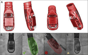
The process of image registration requires localization and tracking of the transesophageal probe position within the X-ray fluoroscopy field. This technique relies on a 3D reconstruction of the TEE transducer head created from a high-resolution CT dataset (Figure 1), which allows the system to predict the fluoroscopic signature of the TEE transducer in various positions. A 2D-3D image registration algorithm is used to match the TEE probe fluoroscopic signature with the predicted X-ray signature based on the 3D reconstruction, allowing the system to track TEE transducer movements in the translational (probe position) and rotational (probe angulation) dimensions during active fluoroscopy. This tracking facilitates continuous automated image registration and overlay in near real-time when fluoroscopy is in use.25,26
 transducer registration status. A: three-dimensional reconstruction of the TEE probe tip using a high-resolution C-arm computed tomographic data set. B: during registration, this data set is used as a template and matched to the observed X-ray projection on fluoroscopy. C: the registration status of the probe tip is displayed as a color overlay, with green denoting successful registration, red denoting unsuccessful registration (panel D), and transparent denoting unknown registration that occurs after fluoroscopy has been inactive for several seconds (panel E). Reproduced with permission from Thaden et al.24")
Transesophageal echocardiography (TEE) transducer registration status. A: three-dimensional reconstruction of the TEE probe tip using a high-resolution C-arm computed tomographic data set. B: during registration, this data set is used as a template and matched to the observed X-ray projection on fluoroscopy. C: the registration status of the probe tip is displayed as a color overlay, with green denoting successful registration, red denoting unsuccessful registration (panel D), and transparent denoting unknown registration that occurs after fluoroscopy has been inactive for several seconds (panel E). Reproduced with permission from Thaden et al.24
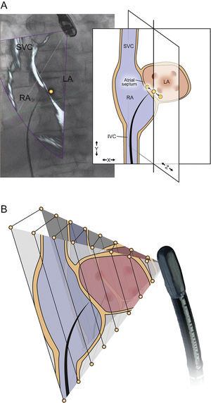
The accuracy of the 2D-3D algorithm depends on precise tracking of the TEE probe head in order to correctly overlay the ultrasound field of view on the fluoroscopic image. Preclinical studies suggested a median registration error of 2-4mm in the plane of the C-arm fluoroscopy image.27,28 Error in rotational registration is amplified at increasing distance from the ultrasound transducer with previous studies demonstrating that a 2° inconsistency in image registration can yield a doubling of error from 1.7mm at 5cm of ultrasound depth to 3.5mm at 10cm of depth (Figure 2).25 Misalignment error (translational error) in image registration is generally most substantial in the direction of the X-ray beam and can be exacerbated by using only a mono-plane X-ray image for TEE probe registration (Figure 2). The accuracy of image registration is improved by using multiple (minimum 2-3) sequential fluoroscopic images of the TEE probe at differing C-arm angles. Despite these limitations, early feasibility studies demonstrated acceptable accuracy at an echocardiographic imaging depth of about 5-6cm,25 although additional validation is needed for clinically available systems.
 or rotational (B) dimensions. Registration is most accurate in the plane of the fluoroscopic image (A, X-Y plane), but this method of registration is vulnerable to error in the direction of the fluoroscopic beam (A, Z dimension). This error can be mitigated by the use of multiple registration angles. (B) An error in rotational registration, whereby the magnitude of the error increases moving from the echocardiographic near field to far field. IVC, inferior vena cava; LA, left atrium; RA, right atrium; SVC, superior vena cava. Reproduced with permission from Thaden et al.24")
Potential sources of registration inaccuracy. Errors in registration can occur in the translational (A) or rotational (B) dimensions. Registration is most accurate in the plane of the fluoroscopic image (A, X-Y plane), but this method of registration is vulnerable to error in the direction of the fluoroscopic beam (A, Z dimension). This error can be mitigated by the use of multiple registration angles. (B) An error in rotational registration, whereby the magnitude of the error increases moving from the echocardiographic near field to far field. IVC, inferior vena cava; LA, left atrium; RA, right atrium; SVC, superior vena cava. Reproduced with permission from Thaden et al.24
Currently available systems allow fusion of live 2D, 3D, and color Doppler echocardiographic images with simultaneous fluoroscopic images. Another important feature of echocardiographic-fluoroscopy fusion imaging is the ability to identify anatomic structures or landmarks in the ultrasound field of view and then document their location on the fluoroscopic image. These annotation points can be used as fiducial markers or points of reference during the procedure. The creation of fiducial markers requires echocardiographic-fluoroscopic image registration as described previously, with the TEE probe transducer ideally imaged at 3 fluoroscopic angles (ideally 45° left anterior oblique, 0°, and 45° right anterior oblique) to maximize registration accuracy. Fiducial markers will remain accurate with horizontal movement of the procedure table, but accuracy may be compromised by vertical (up or down) movement of the procedure table or by changing patient positioning on the table.
Dynamic Versus Static Fusion ImagingDynamic fusion imaging and static fusion imaging have differing strengths and weaknesses. TEE-fluoroscopy, as a real-time imaging modality, provides dynamic imaging which illustrates intraprocedural changes in anatomy. For example, TEE-fluoroscopy fusion can illustrate the nonperiodic intraprocedural distortion of the underlying cardiac anatomy due rigid catheters and devices, which provides important feedback to the operator. In addition, TEE-fluoroscopy imaging provides monitoring for procedural complications that are difficult to assess with 2D-fluoroscopy alone and allows for comprehensive assessment of procedural outcomes. The strength of TEE in tissue visualization and hemodynamic assessment allows the interventional team to evaluate the success of the procedure in real time while the patient is in the catheterization laboratory. However, TEE is limited with respect to field of view and resolution of 3D imaging. In comparison, static fusion modalities such as MSCT and MRI provide high-resolution 3D images in wide fields of view. Additionally, 3D RA reconstructions provide excellent visualization of complex vascular anatomy, especially involving anterior structures, which may be difficult to image with TEE.
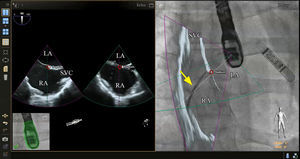
PROCEDURE-SPECIFIC TEE-FLUOROSCOPY FUSION IMAGINGTransseptal PunctureThe ability to perform a transseptal puncture at a precise location remains a critical step for a growing list of transcatheter structural heart procedures. Echocardiographic-fluoroscopic fusion imaging for this purpose has been previously described.24,29–32 Early data indicate that in experienced hands, echocardiographic-fluoroscopic fusion imaging is safe and can reduce the time to successful transseptal puncture.30 Fusion imaging provides simultaneous visualization of the atrial septum and surrounding soft tissue best seen by echocardiography (2D or 3D imaging modes) with the catheters and devices, which are best seen by fluoroscopy (Figure 3). The site of optimal transseptal puncture can be identified by echocardiography. Fiducial markers can be placed at the site of interest on the echocardiographic image and automatically transposed to the “fluoroscopic space” (Figure 3), thereby facilitating more precise localization of the transseptal puncture site on the fluoroscopic image. In the future, incorporation of 3D modeling into fusion imaging may allow for enhanced preprocedural planning and more precise localization of the transseptal puncture site based on patient-specific anatomy.
 and the anterior-posterior axis (right image). In the panel on the right, the bicaval view from the transesophageal echocardiogram is overlaid on the live fluoroscopic image to produce echocardiographic-fluoroscopic fusion. The entirety of the transseptal catheter (yellow arrow) is well visualized by fluoroscopy but is not well appreciated by 2-dimensional echocardiography. Fusion of the echocardiographic and fluoroscopic images provides simultaneous visualization of the transseptal catheter and the relevant soft tissue anatomy provided by echocardiography in a single image and orientation. In this case a fiducial marker was also placed in the echocardiographic space using biplane echocardiography (red circles, left image) and this marker was automatically transferred to the fluoroscopic space (red circle, right image). LA, left atrium; RA, right atrium; SVC, superior vena cava.")
Echocardiographic-fluoroscopic fusion imaging for transseptal puncture. The panel on the left demonstrates typical biplane transesophageal echocardiography, showing the superior-inferior axis (left image, bicaval view) and the anterior-posterior axis (right image). In the panel on the right, the bicaval view from the transesophageal echocardiogram is overlaid on the live fluoroscopic image to produce echocardiographic-fluoroscopic fusion. The entirety of the transseptal catheter (yellow arrow) is well visualized by fluoroscopy but is not well appreciated by 2-dimensional echocardiography. Fusion of the echocardiographic and fluoroscopic images provides simultaneous visualization of the transseptal catheter and the relevant soft tissue anatomy provided by echocardiography in a single image and orientation. In this case a fiducial marker was also placed in the echocardiographic space using biplane echocardiography (red circles, left image) and this marker was automatically transferred to the fluoroscopic space (red circle, right image). LA, left atrium; RA, right atrium; SVC, superior vena cava.
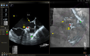
Live echocardiographic-fluorosocopic fusion imaging shows promise for procedural guidance during left atrial appendage occlusion.33 Catheters, wires, and the occlusion device are well visualized by fluoroscopy and the addition of the soft tissue anatomy from echocardiography has the potential to reduce fluoroscopic times and improve safety, although supporting data are lacking. After the transseptal puncture, we have found that a transesophageal echo multiplane angle of 70 to 90 degrees is typically sufficient to simultaneously view the mitral annulus, left atrial appendage, Coumadin ridge, and left superior pulmonary vein when viewed from a right anterior oblique fluoroscopic view (Figure 4). This provides simultaneous visualization of the guide catheter and wires by fluoroscopy and important soft tissue anatomy by echocardiography, facilitating safe and efficient cannulation of the left atrial appendage. Annotation markers at the site of the circumflex coronary artery and the most proximal lobe of the left atrial appendage can be useful to help guide the depth of implantation of the occlusion device. Future incorporation of accurate 3D modeling of the left atrial appendage could help to more precisely plan and localize the best site for transseptal puncture to ensure coaxial alignment of the occlusion device with the long axis of the left atrial appendage.
 and the mitral annulus (double arrows). The panel on the right shows a 2-dimensional (2D) echocardiographic-fluoroscopic fusion image from a right anterior oblique fluoroscopic angle of 29 degrees. The guide catheter is seen by fluoroscopy passing through the transseptal puncture site (yellow circle) and the relevant soft tissue anatomy from the echocardiogram is fused in near real-time (right panel). Fiducial markers were placed at the optimal site of transseptal puncture (yellow circle), the left circumflex coronary artery (red circle), and the tip of the left atrial appendage (green circle). Note that in the fusion image on the right, the guide catheter appears to be abutting the tip of the left atrial appendage when looking at the 2D echocardiographic image overlay. However, this is due to foreshortening of the appendage as the true appendage apex was outside the 2D imaging plane. The true tip of the left atrial appendage marked by the green circle is more distal than it would appear by the 2D image alone. LA, left atrium; LAA, left atrial appendage.")
Echocardiographic-fluoroscopic fusion imaging for left atrial appendage occlusion. The left panel shows a midesophageal view of the left atrial appendage at a multiplane angle of 73 degrees. This view also demonstrates the Coumadin ridge (single arrow) and the mitral annulus (double arrows). The panel on the right shows a 2-dimensional (2D) echocardiographic-fluoroscopic fusion image from a right anterior oblique fluoroscopic angle of 29 degrees. The guide catheter is seen by fluoroscopy passing through the transseptal puncture site (yellow circle) and the relevant soft tissue anatomy from the echocardiogram is fused in near real-time (right panel). Fiducial markers were placed at the optimal site of transseptal puncture (yellow circle), the left circumflex coronary artery (red circle), and the tip of the left atrial appendage (green circle). Note that in the fusion image on the right, the guide catheter appears to be abutting the tip of the left atrial appendage when looking at the 2D echocardiographic image overlay. However, this is due to foreshortening of the appendage as the true appendage apex was outside the 2D imaging plane. The true tip of the left atrial appendage marked by the green circle is more distal than it would appear by the 2D image alone. LA, left atrium; LAA, left atrial appendage.
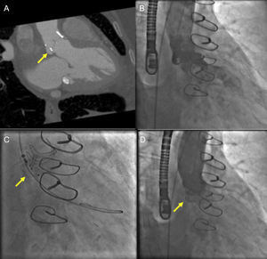
Echocardiographic-fluoroscopic fusion imaging has the potential to facilitate percutaneous repair of paravalvular regurgitation. In our clinical practice, nonfusion MSCT has been helpful for preprocedure planning for aortic paravalvular regurgitation closure (Figure 5). Placement of fiducial markers or superimposed 2D and color Doppler images can help facilitate cannulation of complex aortic paravalvular defects (Figure 6). Annotation markers may be particularly helpful in cases where the paravalvular defect is small or when there is a retrograde (left ventricular) approach to a mitral paravalvular defect. In the previous examples, the defect and cannulation wire may not be well seen by 3D echocardiography alone. One limitation of currently available systems is the static nature of fiducial markers,24 which can limit their usefulness when there is movement of the mitral or aortic annulus in the plane of the image.
 and fluoroscopic guidance for aortic paravalvular leak closure. A: gated cardiac CT angiography demonstrating a posterior aortic paravalvular defect (arrow) in the right anterior oblique caudal view. B: aortic angiography demonstrating moderate paravalvular leak. C: using the CT-derived fluoroscopic angle, paravalvular leak closure is performed using an anchor wire technique with placement of an Amplatzer Vascular II Plug (arrow). D: postimplantation aortic angiography after device implantation (arrow) demonstrates no residual aortic regurgitation.")
Cardiac computed tomography (CT) and fluoroscopic guidance for aortic paravalvular leak closure. A: gated cardiac CT angiography demonstrating a posterior aortic paravalvular defect (arrow) in the right anterior oblique caudal view. B: aortic angiography demonstrating moderate paravalvular leak. C: using the CT-derived fluoroscopic angle, paravalvular leak closure is performed using an anchor wire technique with placement of an Amplatzer Vascular II Plug (arrow). D: postimplantation aortic angiography after device implantation (arrow) demonstrates no residual aortic regurgitation.
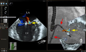
. In this case a moderate jet of aortic paravalvular regurgitation is seen posteriorly (blue color flow imaging). In the fluoroscopic image on the right, various catheters, wires, and the stent frame of the transcatheter aortic valve (*) are better appreciated. The fiducial marker at the site of the paravalvular regurgitant jet is transposed to the fluoroscopic space (red dot), thus facilitating cannulation in this challenging case. LA, left atrium.")
Echocardiographic-fluoroscopic fusion imaging for aortic paravalvular leak closure. The panel on the left shows biplane echocardiography with color Doppler imaging, which allows visualization of the paravalvular regurgitant jet in long- and short-axis views simultaneously. This facilitates precise localization of the jet origin for placement of a fiducial marker in the echocardiographic space (red dot). In this case a moderate jet of aortic paravalvular regurgitation is seen posteriorly (blue color flow imaging). In the fluoroscopic image on the right, various catheters, wires, and the stent frame of the transcatheter aortic valve (*) are better appreciated. The fiducial marker at the site of the paravalvular regurgitant jet is transposed to the fluoroscopic space (red dot), thus facilitating cannulation in this challenging case. LA, left atrium.
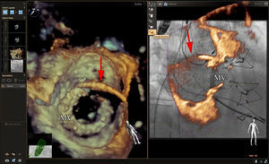
Additionally, we have found that in specific circumstances the addition of extra-echocardiographic or fluoroscopic data can be distracting; these circumstances typically occur when all structures of interest are seen well by a single imaging modality, thus obviating the need for fusion imaging. When guiding mitral paravalvular regurgitation closure we typically facilitate cannulation of the paravalvular defect using 3D echocardiography with an en face view of the mitral prosthesis. This is typically adequate to visualize the guide catheter, wire, and the site of paravalvular regurgitation. In our view, the addition of echocardiographic-fluoroscopic fusion imaging is not necessary in all cases and the echocardiographic data can sometimes obscure the catheters, wires, and mitral prosthesis, which are well seen by fluoroscopy alone (Figure 7). In such cases, the use of live 3D echocardiography in tandem with nonfusion fluoroscopic images with or without an annotation marker at the site of paravalvular regurgitation is most helpful.
 echocardiographic image of a mitral bioprosthetic valve from the perspective of the left atrium. A guide catheter (red arrow) is seen crossing the atrial septum and an anterolateral paravalvular defect has been cannulated. The panel on the right shows a right anterior oblique fluoroscopic view of the mitral bioprosthetic valve with superimposed 3D echocardiographic images (partial slice thickness). The overlay of the echocardiographic information with the fluoroscopic information appears accurate, but 3D echocardiographic blooming, echocardiographic noise, and the additional soft tissue information from the 3D echocardiographic dataset obscures the fluoroscopic view of the guide catheter and mitral bioprosthetic valve. In our experience with an antegrade approach to these defects, 3D echocardiography in conjunction with nonfusion fluoroscopy is typically sufficient for procedural guidance. The addition of a fiducial marker at the site of the paravalvular defect may be helpful, particularly in cases where the defect is small and not well seen by 3D echocardiography. MV, mitral bioprosthetic valve.")
Echocardiographic-fluoroscopic fusion imaging for mitral paravalvular leak closure. The panel on the left shows a 3-dimensional (3D) echocardiographic image of a mitral bioprosthetic valve from the perspective of the left atrium. A guide catheter (red arrow) is seen crossing the atrial septum and an anterolateral paravalvular defect has been cannulated. The panel on the right shows a right anterior oblique fluoroscopic view of the mitral bioprosthetic valve with superimposed 3D echocardiographic images (partial slice thickness). The overlay of the echocardiographic information with the fluoroscopic information appears accurate, but 3D echocardiographic blooming, echocardiographic noise, and the additional soft tissue information from the 3D echocardiographic dataset obscures the fluoroscopic view of the guide catheter and mitral bioprosthetic valve. In our experience with an antegrade approach to these defects, 3D echocardiography in conjunction with nonfusion fluoroscopy is typically sufficient for procedural guidance. The addition of a fiducial marker at the site of the paravalvular defect may be helpful, particularly in cases where the defect is small and not well seen by 3D echocardiography. MV, mitral bioprosthetic valve.
Early data are available demonstrating the safety and efficacy of echocardiographic-fluoroscopic fusion imaging to guide transcatheter mitral valve repair with the MitraClip device (Abbott Vascular).34 Image guidance for transcatheter mitral valve repair remains challenging given the complexity of mitral valve anatomy and the precision that is required in the transseptal puncture and clip positioning. Given these challenges, echocardiographic-fluoroscopic fusion imaging has the potential to improve safety and efficacy in this complex procedure. However, there is a lack of consensus on how fusion imaging is best used to facilitate transcatheter mitral valve repair and there are few data evaluating its impact on outcomes.
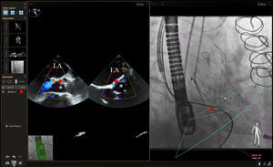
In our experience, the use of fiducial markers to mark the site of the transseptal puncture and the left superior pulmonary vein can be helpful to quickly confirm guide position during the procedure using the fluoroscopic images alone (Figure 8). One of the critical steps in this procedure is adjusting the clip trajectory to ensure that the grasp occurs at the site of mitral regurgitation. This is often well visualized by using a combination of 2D and 3D echocardiography and this remains our primary means of visualization. However, in certain cases, when image quality is suboptimal or if there is significant shadowing from the guide catheter, the use of fiducial markers or live fusion imaging with a 2D-color Doppler or 3D image overlay may be helpful in directing the clip to the site of regurgitation (Figure 8).
. The panel on the left shows a commissural view of the mitral valve with color Doppler imaging showing the origin of the mitral regurgitant jet (yellow arrow). The panel on the right shows a right anterior oblique view of the guide catheter and MitraClip device with live fusion of the 2-dimensional-color Doppler echo image shown on the left. Note that the guide catheter and device position are not well seen on the echocardiographic image on the left. The echocardiographic-fluoroscopic fusion image on the right shows both the guide catheter and its position relative to the regurgitant jet, facilitating precise adjustment of clip position or placement of a second clip. LA, left atrium; LV, left ventricle.")
Echocardiographic-fluoroscopic fusion imaging for transcatheter mitral valve repair (MitraClip). The panel on the left shows a commissural view of the mitral valve with color Doppler imaging showing the origin of the mitral regurgitant jet (yellow arrow). The panel on the right shows a right anterior oblique view of the guide catheter and MitraClip device with live fusion of the 2-dimensional-color Doppler echo image shown on the left. Note that the guide catheter and device position are not well seen on the echocardiographic image on the left. The echocardiographic-fluoroscopic fusion image on the right shows both the guide catheter and its position relative to the regurgitant jet, facilitating precise adjustment of clip position or placement of a second clip. LA, left atrium; LV, left ventricle.
Live image fusion has a benefit in that it is dynamic and responsive to movement of the region of interest. For instance, mitral leaflet pathology changes position with respiration, changes in the cardiac cycle, changes in patient position, and due to tension on the tissues from catheters and devices. Live image fusion will remain accurate regardless of these changes due to its dynamic nature, responding in near real time. By contrast, fiducial markers are static and if the position of the relevant pathology changes due to any of the above factors, these fiducial markers may no longer correlate with the anatomy or structure of interest.
Transcatheter Aortic Valve ReplacementTranscatheter aortic valve replacement has been shown to be a reasonable alternative to surgical aortic valve replacement in select patient groups35–40 and has been rapidly integrated into clinical practice in recent years. Imaging guidance for TAVR varies by institution, but typically relies on fluoroscopy in conjunction with either transthoracic or TEE.41 Cardiac CT is also frequently performed prior to the procedure for aortic annular sizing, making CT-fluoroscopic fusion imaging an attractive option if available, although this technique is also limited in that it is not live or dynamic. Transesophageal echocardiography-fluoro fusion imaging may be useful in some cases by better appreciating wire and device position (visualized well by fluoroscopy) in relationship to the left ventricle, aortic root, and ascending aorta (visualized well by TEE). Limited data also indicate that TEE-fluoroscopy fusion may be useful to determine optimal deployment angle by fluoroscopy.42 Because the aortic annulus can also be accurately measured by 3D-TEE,43,44 a “contrast-free” TAVR procedure can be performed in patients with significant kidney disease. One limitation of echocardiographic-fluoroscopic fusion imaging is that many centers are increasingly performing only periprocedural transthoracic echocardiography for TAVR and currently there is no available system to coregister and fuse live transthoracic and fluoroscopic images.
CONCLUSIONSIn recent years, the number and complexity of transcatheter structural heart procedures has grown significantly while imaging protocols and technology continue to evolve in parallel to facilitate these procedures. Fusion imaging has the unique potential to combine the strengths of 2 imaging modalities to improve preprocedural planning and to potentially improve the safety and efficiency of transcatheter procedures. Currently available TEE-fluoroscopy fusion imaging systems are unique in that they provide live, dynamic imaging that responds to intraprocedural changes in anatomy, allowing the proceduralist to view catheters and devices (by fluoroscopy) and soft tissue anatomy (by echocardiography) in the same image and orientation. It is likely that our use of this technology will continue to evolve in parallel with device and procedural advancements in the field of transcatheter heart interventions. Future work should focus on safety and incremental value added by the use of this exciting new technology.
CONFLICTS OF INTERESTNone declared.