To the Editor:
Many of the electrocardiograms (ECG) that are done every day present artefacts generated by inadequate placement of the electrodes.1 It is very important for the correct interpretation of the ECG that the leads are situated in their assigned places. Variation in the placement of the precordial electrodes is a common source of error (Figure 1). Wenger et al2 determined the differences in their placement among 30 experienced technicians as compared with their correct placement, and found that in over 50% of cases the V1 and V2 electrodes were placed above the fourth intercostal space. These electrodes are the "guide" electrodes for the other leads in the horizontal plane. From a clinical point of view, relevant changes are produced in more than 50% of the automated interpretations of the ECG due to incorrect placement of the precordial electrodes.3 Important alterations are found in all the waves and all the segments of the ECG with the high recording of V1 and V2, identifying images that might lead to false diagnoses and important changes in the P wave,4 and an increase in the negative component is frequently recorded in this latter with the upward displacement of the V1 and V2 leads (Figure 2A). However, an exclusively or predominantly negative P wave in V1, and sometimes in V2, can be recorded with the electrodes correctly situated in persons with certain cardiac disorders that cause left atrial growth. As a result of the high placement of V1, Bayés de Luna5 described the recording of the rSr' morphology accompanied by an exclusively negative P wave as a sign of incorrect placement (Figure 2B). The appearance of an rSr' electrocardiographic pattern in V1 can be predicted if an r'of a certain magnitude is recorded in aVR or a notch in the ascending branch of the S wave in V1 with the electrode correctly placed. Here it is important to stress the importance of the correct placement of the V1 and V2 electrodes, especially in order not to diagnose that a patient has right bundle branch block when rSr' is recorded in V1. The presence of a negative P wave in the same lead, the duration of the QRS £0.1 s and the disappearance of the rSr'morphology after placing electrodes in the fourth intercostal space ensure that it is due to incorrect placement of the leads and not to disease. Additionally, in this case the rSr' morphology presents a narrow r', and although the T wave may be negative, there is no rise in the ST, which distinguishes it from the morphology seen in the Brugada syndrome.5

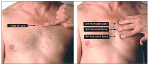
Figure 1. Location of the angle of Louis to identify the second intercostal space and then the third and fourth intercostal spaces.

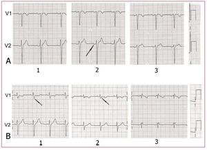
Figure 2. A: P wave with a normal morphology in V1 and V2 in the fourth intercostal space (1); in the third intercostal space (2), although the P wave in V1 presents a morphology that might indicate correct placement, the diphasic P wave in V2 (arrow) indicates a high placement; in the second intercostal space, the alterations are more obvious (3). B: rSr' morphology with a negative P wave in the second intercostal space (3), but not in the third (2), where the third vector presents in the upper branch of the S wave (arrow) and its nadir (arrow) when the electrodes are placed correctly (1).
We must therefore suspect inadequate placement of the electrodes in a patient with no cardiac disorder who has an exclusively negative P wave in V1, especially if this is accompanied by a rSr' morphology. Additionally, the V2 recording of the negative component of the P wave, on many occasions accompanied by a diphasic P wave in V1 with a usual predominance of the negative component, is also a firm indication of the high placement of these electrodes.