Percutaneous Heart Valve Replacement
Percutaneous treatment of heart valves started 2 decades ago in patients with mitral stenosis. In such patients, a stable increase in the mitral valve area could be achieved with balloon dilatation. Complications were infrequent and the outcomes comparable to those obtained with surgery. We learned from this technique that it is possible to reach the heart valves from both the antegrade and retrograde direction, and that we can use different balloon systems mounted on one or two guidewires, double balloons, or special types of balloon, to increase valve area. These procedures have been shown to be safe, temporary flow occlusion is not a major problem, the risk of embolization is low, and complications arising from catheter use (dissection, perforation, tears, rips, and bleeding) are uncommon if the procedure is done correctly. For treatment of stenotic lesions, balloon techniques have proven effective in mitral, tricuspid, and pulmonary valve procedures. However, the medium- and long-term outcomes of treatment of stenotic and calcified aortic valves are not acceptable. In this case, the indications are limited to patients who would be at high surgical risk, particularly those with associated diseases (renal and respiratory diseases, cancer, etc) in whom cardiorespiratory arrest with extracorporeal circulation is not possible.
The development of extracorporeal circulation has allowed safe replacement of native heart valves, with an acceptably low surgical mortality. However, the valves that can be used in valve replacements are limited by strict requirements. The valves implanted should be biocompatible, nonthrombogenic, long-lasting, silent, and resistant. They should also be available in many sizes, be firmly attached, have a low hemodynamic resistance, and complications should be treatable. The implantation technique is also subject to drawbacks. The patient requires general anesthesia and the chest, pleura, and pericardium need to be sectioned. The technique may also require multiple cannulations, extracorporeal circulation, heart arrest with cardioplegia, drug infusion, and blood transfusions, and valve substrate modification with possible structural damage, and possible hemodynamic repercussions for the cardiac chambers. In addition, the risk of infection needs to be considered as well. Furthermore, we should bear in mind the high costs of the operation, the staff and surgical team required, and the care associated with the postoperative recovery.
Nevertheless, the integration of knowledge acquired from a range of surgical and percutaneous procedures, particularly those that use balloon procedures, stenting, metal heart valves, and bioprosthesis, has enabled us to take up new challenges, such as percutaneous implantation of heart valves.1
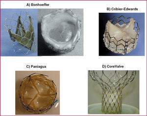
Valves with biological membranes have been developed that can be mounted and sutured onto a foldable platform with stents, and that have a small cross-sectional area to make their introduction, manipulation, and deployment over the native valve easier. This has led to their successful implantation in patients, where they remain with their properties intact for a long time. The outcomes of these techniques have been promising. Bonhoeffer et al2 implanted a dissected bovine jugular vein with a venous valve mounted an irradiated plantinum stent (NuMed) (Figure 1A). This valve was introduced via a catheter along an 18-Fr introducer and deployed with a 22 mm diameter balloon at the right ventricular outlet tract, within the graft material. This experience marked the start of the era of percutaneous heart valve replacement.

Figure 1. Different models of percutaneous valve prosthesis.
Percutaneous aortic valve replacement was first done by Cribier et al3 with an antegrade transseptal approach that passed through the left atrium to the left ventricle, finally reaching the aortic root. This is a demanding technique and tolerance is limited in some critically ill patients. The valve, with 3 leaflets, is from equine pericardium, and is mounted on a stainless steel stent 14 mm long and 23 mm in diameter with high radial stiffness and little flexibility (Figure 1B) (Percutaneous Valve Technologies-Edwards Lifesciences). It is mounted on a balloon measuring 22 mm in diameter and 30 mm long (NuMed). The 24-Fr device is introduced via the femoral vein and slides along a rigid metal 0.035 inch guidewire externalized via the left femoral artery. The exposed stent mounted on the balloon passes through the atrial septum, the left ventricle, and the different intracardiac structures (mitral valve, chordae, trabeculae, and aortic valve), with the risk of snagging and/or damage to these intravascular structures before finally reaching the calcified valve. High frequency pacing (220 beats/min) with a pacemaker is applied during valve implantation procedure to reduce the risk of prosthesis slippage or embolization. With the technique, flow occlusion times of less than 30 seconds can be achieved and it is possible3 to obtain residual gradients of less than 5 mm Hg and a mean valve area of 1.7 cm2. Some patients present minor perivalvular leakage. Moreover, the initial mortality was high and associated with use of large diameter prosthesis and with the presence of high-risk factors in the treated patients.
The retrograde approach was first attempted by Paniagua et al,4 who used a porcine pericardial valve with a 2 mm cross-section (Endoluminal Technology Research; USA) mounted and sutured onto an irradiated plantinum stent (Figure 1C), and deployed with a 20 mm by 30 mm balloon (NuMed Inc.). The valve was advanced with a 16-Fr introducer until reaching the abdominal aorta (after prior balloon dilatation according to the usual aortic valvuloplasty technique), where it was positioned over the aortic valve, thus achieving a final valve area of 1.6 cm2 with no significant perivalvular leakage. The Cribier-Edwards valve has also been used with a retrograde approach, although delivery through the convoluted and calcified femoral, and iliac arteries of elderly patients and through the calcified, and deformed aortic valve itself can cause problems due to its high caliber (24 Fr). Encrusting of the valve at the valve commissure or even valve breakage may occur as a result of fracture during predilatation or excentric placement of the metal valve. The subsequent passage of the valve mounted on the balloon catheter is therefore impeded. Recently, a special catheter has been developed that allows the entire device to be steered and deflected. The device can therefore be guided through the center of the valve, thus ensuring successful implantation.5
The Cribier-Edwards expandable balloon valve has recently been successfully implanted in 7 very high-risk surgical patients with calcified aortic stenosis.6 The novel aspect was the left ventricular transapical approach by means of a direct needle puncture without extracorporeal circulation. The strategy is promising as the surgical technique is less aggressive and complex and it brings together surgeons and interventional cardiologists. The technique will soon be used for both implantation and repair of valves because it allows direct access to the aortic valve and the mitral valve apparatus.
Recently, Grube et al,7 with a retrograde approach, implanted an equine pericardial valve mounted on an hour-glass-shaped stent in patients with aortic valve disease. The lower part of the self-expanding Nitinol stent (designed by Jacques Seguin, CoreValve), where the pericardial leaflets are sutured, has a higher radial strength to allow it to be deployed and expanded in the aortic ring where it can force aside the calcified leaflets. Its narrower middle part accommodates the coronary sinus, preventing limitation of coronary flow. The upper part is wider and is designed mainly to stabilize the stent and ensure that the valve is positioned centrally (Figure 1D). Implantation of this device (initially 24-Fr gauge) takes longer for placement and deployment. Given that the procedure takes more than a minute, implantation currently requires hemodynamic support in the form of femoral-femoral extracorporal circulation (femoral vein-right atrium to femoral artery-abdominal aorta). Initially, the very rigid nature of the system made the procedure a complex one, and so ventricular perforation, incorrect valve positioning, and prolonged intervention times were common, resulting in blood sequestering by the legs and metabolic acidosis. With the second generation of this valve and the new stent design, the thickness of the metal was reduced and the wialth of its upper support was extended. Moreover, by switching to a porcine pericardial membrane, improving the suture technique, and deploying the device with a lower caliber catheter (21-Fr in the valve segment and 14-Fr in the catheter body), the outcomes of the procedure have improved markedly whereas mortality and procedural complications have decreased.
Currently, other valve systems, in particularly self-expanding ones, are being tested in animal models. Some of these will be studied soon in patients. The models described previously will be compared with surgical treatment and programs will be established for patients with acceptable risk, comparable to those who undergo surgery. The initial findings suggest that percutaneous valve implantation will soon be a valid option in a substantial number of patients and these percutaneous procedures will be lower risk than surgery.
Percutaneous Repair of Heart Valves
Treatment of mitral valve regurgitation is one of the biggest challenges facing interventional cardiologists.8,9 Currently, several surgical techniques are used, such as mitral valve replacement, particularly in patients with structural damage. In cases of valve dysfunction, segments can be modified by either edge-to-edge suture (Alfieri technique8) or annuloplasty to reduce the mitral annulus diameter, so improving leaflet coaptation.
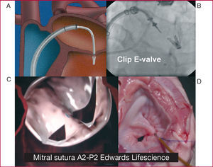
The technique of edge-to-edge suturing of the mitral valve (Alfieri technique) can also be done percutaneously with specific systems that can reach the valve with special therapeutic catheters. The edges can be joined either with a clip (E-Valve clip) (Figure 2A and B) or with suction-and-suture of the edges (Edwards suture) (Figure 2C and D) in the central region of the mitral valve (A2-P2). These techniques have been shown to be useful in patients with a central regurgitation jet. The E-valve clip was the first of these devices to be used in our group, with excellent results sustained for 2 years after clip deployment.10 The Everest I program11 confirmed the feasibility and safety of this technique. In the ongoing Everest II study, the outcomes are being compared with those of surgery. The preliminary findings seem favorable and more than 70 patients have been treated with this system. This technique requires close collaboration between imaging cardiologists, interventional cardiologists, and anesthetists. Safe and optimal placement during clip deployment requires transesophageal echocardiography under general anesthetic and fluoroscopic imaging for reference. Moreover, the clip device is special and rather ingenious, with a 24-Fr diameter. Experience is needed to place it centrally in the mitral valve apparatus. The device can be manipulated from where it is introduced into the right femoral vein and during its passage through the atrial septum. This allows sufficient control of all the elements of the device to ensure the mitral valve leaflets are fastened.

Figure 2. Techniques for securing the edges of mitral valves. A and B: E-valve clip. C and D: Edwards Lifescience suction-and-suture device.
Another system with a suction-and-suture device was developed by Masiano et al.12 The catheter has a lower caliber (12-Fr) and also requires excellent 3-dimensional guidance to apply suction at the most appropriate point of the anterior leaflet and then the posterior leaflet. In this suture system, the fastened area is less than when the clip device is used, and so greater precision is required for placing the suture point to optimize the reduction in mitral regurgitation.
The second group of techniques for the treatment of mitral valve regurgitation corresponds to systems that bring the mitral leaflets together by acting on the mitral annulus (annuloplasty), so reducing the distance at the base of the leaflets and optimizing their overlap and coaptation during systole. The mitral valve apparatus is a complex system. Its elements include the left ventricular free wall, papillary muscles, the corresponding chordae tendinae, leaflets and the base where they are attached, and the mitral annulus. All these components play an important role in ensuring stable coaptation of the leaflets to prevent mitral regurgitation in the high gradient that exists between the left ventricle and the left atrium. If any of these components is affected, as occurs in left ventricular dilation, the mitral annulus is dilated leading in turn to mitral regurgitation.
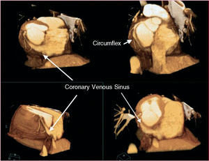
The known anatomical relationship between the coronary sinus (CS) and the mitral annulus (Figure 3) and the experience with using the coronary sinus in multiple catheter treatments has led to the development of techniques that allow a stable approach. Cannulation and therapeutic use of this conduit has made possible percutaneous procedures that act on the mitral valve. Specific devices have been developed that can be introduced via the CS in order to bring the posterior mitral leaflet closer to the anterior one when regurgitation is due to mitral annulus dilation.

Figure 3. Three-dimensional reconstruction from multidetector computed tomography images that show the relationship between the venous sinus and the circumflex artery.
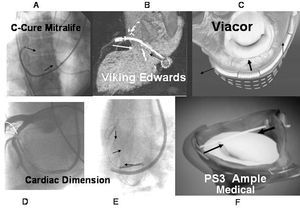
Of these techniques, the first to be applied in humans was the C-Cure device, which was first used by our group in 1999.13 After evaluation in animal models of both acute and chronic diseases, the C-Cure device (Mitralife Inc. USA) was temporarily applied with a 10-Fr catheter in a small series of patients.13 The system is introduced through the right jugular vein until reaching the CS, where it is deployed by changing its elongated shape into a concave one, thereby compressing the CS, which in turn compresses the segment adjacent to the mitral annulus (Figure 4A). It was shown that the system was more effective at reducing mitral regurgitation when acting on the medial segment of the posterior leaflet (P2), as shown by instantaneous Doppler echocardiography taken along with the pertinent hemodynamic variables. Although the device was shown to be effective at reducing mitral regurgitation, its placement and anatomical location were not stable and safe enough for the patient, and so it was not permanently implanted. Furthermore, when the constriction was done with support deeper in the CS, pinching of the circumflex artery occurred, reducing coronary artery flow. This effect was reversible once the traction effect on the artery had been withdrawn. This is considered a limitation in devices that use CS as the site of application for constriction of the mitral annulus. Recently, Masselli et al14 further confirmed this observation after detailed anatomical evaluation. According to these authors, 64% of the patients had a branch of the circumflex artery and 16% had an obtuse marginal branch located between the CS. Therefore, the percentage of patients at risk of induction of ischemia is high (80%) with implantation of these devices. These investigators also reported that the mean distance between the CS and the mitral annulus was 9.7 (3.2) mm above the annulus, with a maximum distance of 19 mm.14 This indicates that the larger the distance, the less the effect on the annulus. We therefore consider necessary noninvasive assessment such as computed axial tomography or nuclear magnetic resonance, or left coronary angiography including the venous beds in order to establish vascular correlations, to select the patients most likely to benefit from this technique, and to prevent complications.

Figure 4. Systems for constriction of the mitral valve.
Another system for constriction of the mitral annulus via the CS is the Viking device manufactured by Edwards Lifescience (Webb et al15). A Nitinol bar-spring with 2 self-expanding stents attached at either end is implanted in the CS using a catheter (Figure 4B). The device is implanted in its stretched confirmation, but it shortens as it comes up to body temperature. On shortening, the bar exercises a constrictive effect which affects the mitral valve and functional mitral regurgitation is reduced. However, of the series of 4 patients described initially, only 1 had a sustained effect after 6 months due, essentially, to bar fracture.
The Viacor system, used in animal models of acute16 and chronic disease,17 consists of a catheter that is introduced through the subclavian vein until the CS is reached. It has 3 conduits that allow 3 metal bars of Nitinol to be introduced, causing the catheter to straighten in the segment located in the CS, so exerting pressure on the mitral annulus (Figure 4C). Unlike the devices described previously, it is supported at either end thereby applying a divergent force at these ends that can attenuate the straightening. The device has started to be used in patients in surgery, and a program for permanent implantation in patients is being prepared.
The Cardiac Dimension device, which has been used by Kaye et al18 in acute cases and Maniu et al19 in regurgitation models in animals in both acute and chronic disease, reduced the mitral annulus and functional mitral regurgitation. The nitinol device is placed within the CS using handles that serve as anchors, and the metallic section that connected them is tensed (Figure 4E). As before, some side effects have been described in the circumflex artery (Figure 4D). We still await the use of this device in patients.
Another transvenous model in the CS is the Q-Care Quantumcore, based on inducing a scarring response (fibrosis) after application of electrofulguration (65ºC over 10 s) in the CS sulcus corresponding to the base of the posterior mitral leaflet, so leading to annulus retraction. This device has yet to be tried in patients.
There are two possibilities of applying traction without relying on mechanical effects transmitted through the venous sinus. One of these is the PS3 system (Percutaneous Septal Sinus Shortening) supplied by Ample Medical Inc. In this system the shortening traction is established between the CS and the atrial septum, and the device is held in place with a metal bar in the CS, close to the P1-P2 segment, and a chord across the left atrium that is anchored in the atrial septum. An Amplatzer system as used to close the foramen ovale in order to distribute the support force throughout the atrial septum (Figure 4F).
After experiments in animals by Rogers et al,20 our group recently implanted this system for the first time in 2 patients before surgery. In these patients, the reduction in regurgitation was evaluated and found to be satisfactory. This alternative is not subject to the drawback of negatively affecting the circumflex artery because the traction is applied in a more lateral plane.
Along similar lines, devices such as Mitralign are now in development to reduce the distance of the mitral annulus using a left transventricular approach. This allows the posterior sulcus to be accessed on the ventricular side with catheters and special suture systems. This in turn allows intraventricular points of support to be established and attachment with their respective clips although the technique has so far only been tried in animals.
The technology is clearly advancing and we are optimizing the support points and approaches to the valves. Recently, investigators have used a combined surgical and percutaneous technique through puncture of the ventricular apex after minimal thoracotomy. The introducers were advanced through the apex of the left ventricle, and it was possible to place a balloon-expandable valve in the aortic position. With this success, not only has implantation of percutaneous valves by a transapical approach been made possible, but also repair of the mitral valve with much greater control at sites that would be difficult to access with catheters. The big challenge at present is the atrioventricular implantation of percutaneous valves and, particularly, mitral valve implantation. These atrioventricular systems are limited mainly by the large annuli. In animal models, valves have already been placed in the mitral position, but within a previously implanted bioprosthesis.21
In this review of recent developments in both the implantation of percutaneous valves and their repair, we can predict that the next decade will see the second big revolution in interventional cardiology, namely, percutaneous treatment of valve disease.
Correspondence: Dr. J.A. Condado.
Laboratorio de Hemodinamia.
Hospital Privado Centro Médico de Caracas.
Urb. San Bernardino. Caracas. Venezuela 1011.
E-mail: Condadoj@telcel.net.ve